|
|
HOME CALENDAR OF EVENTS LOCOMOTIVE TYPES SIGNALING DCC MODULAR LAYOUT MEMBERS MEMBERSHIP APPLICATION OUR HISTORY LAYOUT TOUR FALLEN FLAGS CONSTITUTION
|
|
Page 2
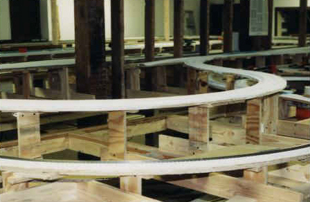
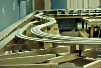
| While the demolition work was under way, the layout committee was busy taking measurements of the available space, transferring them to a CAD program, and set out designing a layout that would best utilize the space available. The layout room measures 34 X 41ft which provided ample space for a moderate sized layout. The bench work was standard L-girder and risers using Homasote on 3/4" plywood. This gave us the most flexibility with elevations ranging from 36" to 58". 1 X 4 cross-members were used throughout except in the mountain areas where 2 X 4's were utilized. We realized that the extra weight created by mountain scenery would need additional support and we needed to maintain stability in that area as we anticipated the use of a lot of bridges. We eventually used 800 pounds of plaster in that area. |
 |
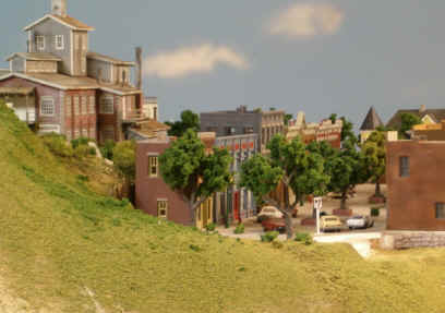
The North Peninsula, along with the rest of the layout, utilized Homasote over 3/4" plywood on L-girder construction. This provided a very solid base for the track. Later called Allenton, and fully developed, below are some views of what the area looked like in 2009. |
|
Coming up with a plan to best utilize the space available was quite a task. Six different designs were tried on a CAD program until the layout committee had the right one. Once that was established, the refinements to it were easy. We had to have 42" aisles to maintain proper traffic flow and to give operators ample "elbow room". |
|
Looking North from Sacred Mountain very early in the construction stage, before track was laid. Note the 2X4 cross members. This was done for added strength to support the mountain scenery to come later. All the curves were super elevated for a realistic look. Below it you will see the same view as it looked in 2009. See the completed Devils Gulch and Sacred Mountain |
|
|
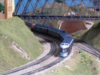
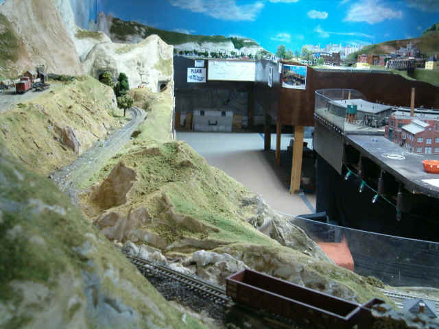
After 15 years, a double mainline HO and HOn3 layout on multiple levels with branch lines leading to a double-ended staging yard and other areas with complete scenery and details was a popular attraction. The layout was a walk-in design with walls and scenery separating the various areas so the visitor cannot see the whole layout at once. Actually, the construction of the building with a bearing wall down the middle of the layout room made this the only possible choice. The CAD program created the blueprints for construction. A major consideration was aisle space, and 42" aisles were a must if we were to accommodate visitors. We didn't want our guests to have a sterile view through a window, instead invite them to wander throughout the layout. Members were always there to answer questions. Lexan protected some of the more delicate lower areas. The main lines had a maximum grade of 1% and a minimum radius of 50". We did not want a spaghetti-bowl effect that we noticed on many club layouts. Instead, the design created a series of distinct dioramas separated by scenery or backdrops. Trains run through each scene only once. Great care was taken during the early stages to provide a proper base for trouble-free operation. This was necessary to allow the smoothest mainline operation possible. Much of the mainlines were not easily accessible as they wound through mountain terrain, behind buildings, and under the main city. |
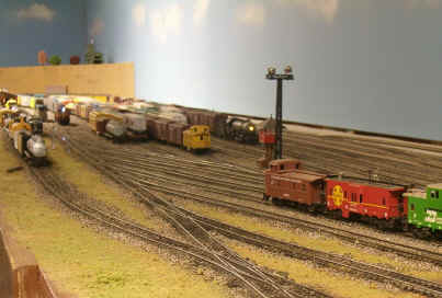 |
This is the South end of the Proviso Yard. This yard was 45 feet long and could hold 750 cars. It was double ended, and required two operators. Most of the switching was done on this end. The track on the left is actually an isolated programming track. |
| The Proviso Yard was the focal point of activity on the layout. With a capacity for 750 cars, this North-South classification yard, designed for two operators, was the traffic hub. Nearly every piece of freight passed through this yard at some point in its journey. The operators here were the busiest on the layout. The double-ended Argentine and Zion Staging Yards below the Proviso Yard and Union Station had the capacity to store 12 40-car trains. With more than 4200 feet of track (70 scale miles of Atlas code 100 & Micro Engineering code 70) laid, the operational possibilities were enormous. |
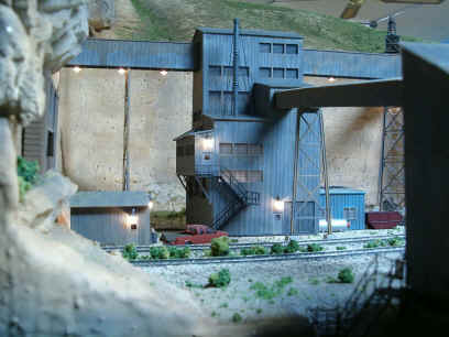
| Pouring "concrete" at a new diesel engine service facility at the south end of the Proviso Yard. Patching plaster was used here for several reasons. It has a longer setup time allowing you to work with it and doesn't crack when cured. I would like to see the real guys do it this fast. | 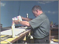 |
| 154 Peco turnouts powered by Tortoise switch
machines were utilized throughout and had proven very reliable. The
dual gauge and narrow gauge turnouts were built in place and were hand
thrown. 18 walk-around cabs (5 mainline & 13 local) were custom
built based on a design that appeared in Model Railroader many years
ago, and proved to be very reliable.
We converted to DCC for greater flexibility in 2003 using the Digitrax system. Because of the size of the layout, four boosters were needed. We operated between 18-24 trains during operating sessions and open houses, though not necessarily all at the same time. |
HOME CALENDAR OF EVENTS LOCOMOTIVE TYPES SIGNALING DCC MODULAR LAYOUT MEMBERS MEMBERSHIP APPLICATION WEBRINGS - LINKS OUR HISTORY LAYOUT TOUR FALLEN FLAGS CONSTITUTION
Photos and text on this site are © 1977 - 2019 Sheboygan Society Of Scale Model Railroad Engineers, Ltd. All rights reserved.
Last
Updated: Monday, January 28, 2019