HOME CALENDAR OF EVENTS LOCOMOTIVE TYPES NEWS SIGNALING DCC MODULAR LAYOUT MEMBERS MEMBERSHIP APPLICATION OUR HISTORY LAYOUT TOUR FALLEN FLAGS CONSTITUTION
ATSF
Dual Track ABS Signaling ![]() Signaling
overview
Signaling
overview ![]() SE8C
& RR&Co
SE8C
& RR&Co ![]()
Detection & Signaling on our Modular Layout
The Society's modular layout is taken to shows many times each year. Its purpose is to show the history of railroads as well as demonstrate how railroads do their job. Since we had added operational signaling to our permanent layout, we investigated to see if it would be feasible to do the same on the modular layout. The logistics of having prototypically accurate signaling on a layout that has to come apart was daunting. "It can't be done" was the answer we got from many. Our DCC Head kept going through various possibilities, dismissing them as much too difficult until he came up with a way that would work and be relatively simple to implement.
This is the only modular layout in the United States that employs fully operational block signaling and computer control. We have learned that there are a few others who have followed our lead on a limited basis, but not to this extent. We could have done it using Team Digital products as well, but chose to stay with Digitrax because of greater familiarity with them and company support. Either way we could have achieved the same effect, but we also wanted to track train movement as we operate multiple trains on each mainline. The computer option best met our needs, and also allows us to run fully automatic.
What we did was this. We have two four module sets and six three module sets, plus the yard, each with a number of turnouts and three mainlines. We prewired 44pin sockets for SE8C boards. Those sockets were wired to terminal strips 1” away.. They were secured it to the underside of one of the modules in each 4 module set. They are located halfway around the layout from each other. For detection, each module set received a BDL168. The inside rail of each track was isolated within the module set and wired for detection. A Molex plug connected to the isolated rails was used to connect the modules together within the set once assembled, using 14ga stranded wire. The buss line connections were made more robust to accommodate DCC. Each module set uses at least one DS64 for turnout control. There are 11 DS64s. All of these devises are tied together with LocoNet cables after assembly, except for modules that have multiple boards. In those cases, short LocoNet cables are left in place when stored.
|
|
|
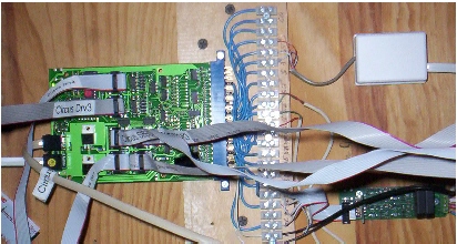
Here
you see an SE8C mounted under a module. The edge connector is wired to
a
terminal strip, making it easier to make connections, and for
troubleshooting.
Once the modules are assembled, the pre-labeled LocoNet and signal
cables are
connected to the board, and all other boards they need to connect to.
It makes
the layout plug-n-play, almost as easy as before all the features were
added. There's just more things to plug in. |
Signals
were placed at the entrance of each module set for each mainline, as
well as for
sidings. We generally
run the two outside mains in the same direction with the center main
running the
opposite way, the same as it is done at the Museum of Science &
Industry in
|
|
|
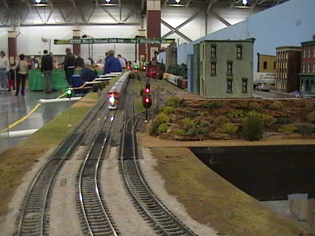
A Santa Fe passenger train approaches on the center line. Signals in the foreground and in the distance change automatically depending on train location and turnout position. |
Custom
lengths of ribbon cables for the signals, as well as Loconet cables of
varying
lengths were made up and labeled. On sets of modules of three or less,
we added a DS64
and BDL168 for turnout control and detection, creating one detection
block for
those on each mainline and sidings. Some of the corner modules have recently been
added as detection
zones. Each turnout is operated with a Tortoise controlled
with a DS64.
On the sets that go together there are the standard Cinch-Jones module buss line plugs along with multi-pin Molex plugs to link the detection zones together, as well as lighting where needed. At the point where two module sets join, gaps were cut about four inches from the end of each set on one rail. That section of rail, plus the section of track installed at setup to join the modules, is tied to the main buss outside a detection zone. There is also a 14V DC buss line that travels all the way around to power all the devises. The layout is divided into power districts, using three DB150 boosters. The DCS100 command station does not power any track, and is isolated with an LNRP.
The modules were originally constructed to the NMRA module standard established more than 30 years ago, measuring 2.5 X 4ft with three mainlines, AC outlets and cords on each module, and the standard Cinch-Jones color coded plugs and jacks for the mainline buss. When the conversion to DCC was made, we originally kept it backwards compatible so it could still interface with modules from other groups, however the AC connections on each module have since been removed since regulations no longer allow them. We did add a 14VDC bus that modules can p0lug into for board or lighting power if needed. Cinch-Jones to Power pole adaptors are available for those using the newer unofficial standard. Operating with other layouts in DC however, is no longer possible, since the block detectors accept DCC only.
We have several different ways to set up the layout, but it was configured so that there was a UP5 panel about every four modules, both inside and outside, so operators could plug in anywhere, however Train Controller runs the layout most of the time. The only times throttles are used is for some extra switching action at various locations or to manually change out trains. We have different files on the computer with the various track plans we use and call up the file based on how it is setup. All the logic is preset in the file.
(A note about UP5 throttle jack panels. We have seen cases where groups will substitute generic telephone jack panels to save money. It usually winds up costing more in the long run as there is no protection built in for shorts, and no easy way to power throttles outside of LocoNet. Do it right the first time and avoid the frustration later.)
When it’s all set up we have 60 detection blocks and 42 signals. The 36 X 40ft layout, with 42 modules, can be setup in 4 hours. We then plug a laptop into it with two Locobuffer USB's and load Train Controller and Decoder Pro.. Schedules are started and the computer runs the layout all day. With safeguards in the software, no two trains can occupy the same block. There is a 12 track staging yard where we can change out trains, which is also wired for detection. All mainline and yard turnouts use Tortoise machines controlled by stationary decoders. We had problems in years past where children would throw a turnout when nobody was looking and caused trains to go where they weren't supposed to. Now they just snap back when they let go. The addition of a barrier also helped keep youngsters back.
|
|
|
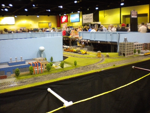
This is the entrance to the 12 track staging yard, which is flanked by two crossover modules that allow access to all yard tracks from any mainline in either direction. This was an opportunity to display a lot of signal options. |
Visitors at shows love to see the signals change as trains pass. Many ask what the signals mean, or how it's done. Because we aren't tied up running the layout, we have time to teach people what it's all about. This signaling is loosely based on the ATSF ABS standard.
Photos and text on this site are © 1977 - 2018 Sheboygan Society Of Scale Model Railroad Engineers, Ltd. All rights reserved.
Updated: Saturday, August 18, 2018